


Siemens Healthineers MedMuseum
Discover (hi)stories
Reinforcements for surgeons

X-rays in the operating room
Reinforcements for surgeons
Nowadays, it is compulsory to explain operations to patients in advance, as every procedure carries certain risks – although a risk of explosions is presumably no longer one of them. In the early days of X-ray technology, things were quite different. Until the 1930s, the high-voltage cables of the X-ray equipment ran through the room without insulation and therefore not only exposed staff to the risk of electrical accidents but could also generate sparks. When combined with ether, one of the most common anesthetics at the time, these sparks could even cause explosions. However, that is not the only reason why it took so long for X-ray technology to become established in the operating room.

An X-ray examination using the Unipuls X-ray apparatus: The exposed high-voltage cables ran from the induction coil (in the cabinet) to the tube. Advertising photo, 1910

The photo of this dental X-ray system from 1909 clearly shows how close the physician and patient came to the exposed high-voltage cables.The photo of this dental X-ray system from 1909 clearly shows how close the physician and patient came to the exposed high-voltage cables.

Electric “firework” in a high-frequency laboratory, c. 1910
In order to perform a successful operation, the physician must be able to see as much as possible, which means that the operating area must be brightly illuminated. This was precisely the problem when it came to monitoring operations using fluoroscopy, because the fluoroscopic image was so weak that either the OR had to be completely darkened or physicians had to resort to using aids such as cryptoscopes. In addition, the physicians’ eyes had to adapt to the darkness for between 15 and 45 minutes prior to each fluoroscopic examination so that they could make out the finer structures in the fluoroscopic image. It was only in the mid-1950s that physicians received reinforcements in the form of a device that could intensify X-ray images.

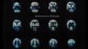
These two examples give an impression of what fluoroscopic images looked like. Tissues that absorbed less X-radiation appeared as brighter areas in the image. Bones, for example, which have a high X-ray absorptivity, appeared as dark areas on the fluorescent screen. Marketing brochure for the Siemens X-ray Sphere, 1951

The solution came in the form of a device known as the cryptoscope – a pyramid-shaped box with a viewing window on the top and a fluorescent screen on the bottom that allowed fluoroscopic examinations to be performed even in bright rooms. Photo from 1897
A fluoroscopic examination with the cryptoscope and the Nanos portable X-ray system: The development of compact and mobile X-ray systems was another key milestone in the use of X-rays in the operating room. Advertising photo from 1932

Some readers may remember similar devices known as shoe-fitting fluoroscopes. Here, a housing containing a transformer and X-ray tube was fitted with a viewing box that fulfilled the same purpose as a cryptoscope: Regardless of the ambient illumination, the image on the fluorescent screen could be used to determine the correct shoe fit – and it could even be viewed by several people at once. The devices were still found in German shoe shops until the 1970s.
By the 1930s, people were already coming up with suggestions for how the fluoroscopic image could be intensified electronically, but these electronic X-ray image intensifiers weren’t ready for the market until the 1950s. When they did arrive, the devices allowed physicians to discern details in the fluoroscopic image even in daylight conditions, considerably reducing the time needed for examinations – which also only required about a third of the previous radiation dose.
To facilitate the work of physicians in the operating room, portable fluoroscopy units were also developed. Here, the image intensifier was permanently attached to the X-ray tube in a construction that, because of its shape, was referred to as the C-arm. The advantage of this construction was that the image intensifier and the X-ray tube were always in the ideal position relative to one another. By rotating and pivoting the C-arm in numerous directions, physicians could select the best position for the examination at all times. Looking back, it’s clear that the introduction of the image intensifier marked a turning point in development and led to a breakthrough for X-ray technology in the operating room.

Schematic diagram of the mode of operation of an image intensifier with an optical viewing system: SRW marketing pamphlet, 1958

In the image-intensifier tube, the X-rays would strike the input fluorescent screen and produce a fluoroscopic image, just as in a normal fluoroscopic examination. The difference here, however, was that the input screen was connected to a photocathode that emitted electrons when struck by light from the fluorescent screen – the brighter the light, the more electrons were emitted. In the image intensifier, the electrons were then accelerated by an electric field and focused onto the output fluorescent screen by electrodes in the electron-optical system. Although the image produced on the output screen was smaller, it was crucially several times brighter and could either be viewed through a lens system or captured using a camera.

The first image-intensifier fluoroscopy system from Siemens was launched in 1957 and consisted of a C-arm with an image intensifier and an X-ray tube, as well as the Monodor portable X-ray system.

The Siremobil 4, 1987
The shape of the C-arm was so suited to applications in the OR that even cutting-edge devices, such as the ARTIS pheno system from Siemens Healthineers, still use this construction today. In terms of technology, however, Siemens Healthineers is continuing to break new ground with ARTIS pheno – at the time of its introduction the only robotics-equipped C-arm system on the market. It recognizes the position of the tabletop at all times and aligns itself to the tabletop with every movement. Thanks to memory positions, the system can move the C-arm out of the operating area quickly if necessary, giving the surgeon and the operating team free access to the patient. The C-arm can then be moved back to exactly the same position again for further imaging. This means results can be checked directly, even while the operation is still in progress.
Accurate and detailed imaging not only helps physicians with their work, but also benefits the patient directly. It is a vital part of minimally invasive surgery – that is, surgery that has the least possible impact on the patient. For a long time, this type of procedure was used primarily in cardiovascular surgery and neurosurgery – for example, to insert “stents” (supports used to treat the narrowing of blood vessels). Modern hybrid ORs equipped with high-tech equipment, such as ARTIS pheno systems or SOMATOM computed tomography (CT) scanners, are helping other disciplines – such as orthopedics and trauma surgery – to perform more and more minimally invasive operations as well. This type of intervention is gentler than open surgery and, as such, is particularly important for treating older patients or patients with preexisting conditions. Moreover, minimally invasive surgery can significantly shorten the recovery period and the length of hospital stay. For instance, pelvic fracture patients who receive a minimally invasive screw fixation procedure can walk with full weight-bearing just one day after the operation. Nowadays, it’s impossible to imagine medical imaging without software solutions. For example, syngo DynaCT captures hundreds of individual images and takes just a few seconds to convert them into 3D images that resemble those from CT scanners. Particularly important information from the generated images can be superimposed on fluoroscopic images during the examination to allow physicians to navigate the procedure even more precisely.
Even computed tomography (CT) itself is now used directly in the operating room. In these systems, the gantry slides over the patient on rails without requiring them to be moved or repositioned for the scan. When the system is not in use, it can slide back to its parking position. The rails themselves are set into the floor so that they do not present an obstacle for equipment trolleys or beds.
Electronic image intensification, robot-assisted C-arm systems, and CT scanners – in the early days of X-ray technology, surgeons presumably couldn’t even have imagined the benefits of these accomplishments. However, it is thanks to achievements such as these that X-ray imaging is no longer simply a useful tool when preparing for an operation, but now also plays a key role in the surgeon’s work inside the OR.

Expert for History Communication and Historian at the Siemens Healthineers Historical Institute